How to make your own computer from electronic components
The electronic building blocks that make your PC tick
Binary maths
OK, we're almost ready to make our adding machine, but before we do that you need to know about the binary number system. Numbers can be represented in many different ways.
In our day-to-day lives, we most often interact with the decimal system. In this system, we have ten symbols, the value of which depends on its place, with each place having a value of ten times that of the place to its right.
In the number 133, for example, the 3 on the far right is simply worth 3. The second 3, however, indicates 30, and the 1 on the left-hand side indicates 100. The value of the number as a whole is the sum of all three places.
Binary is a bit different. Instead of having ten symbols, it has only two: 0 and 1. Because there are only two symbols, each place in a binary number is worth twice that of the number to its right, not ten times.
Take the binary 011, for example. The 1 on the far right is worth 1. The 1 next to that, however, is worth 2. Just as before, the value of the number as a whole is the sum of both places, so 011 in binary is 3 in decimal.
Note that binary might represent numbers differently, but it works in the same way. This means that all the usual tricks for adding, subtracting etc, still work.
Binary is important in computers because it's easy to manipulate and store via electronic mediums. A 1 in binary can be represented by the presence of electric flow (a closed switch) and a 0 by the absence of flow (an open switch).
Sign up for breaking news, reviews, opinion, top tech deals, and more.
Half adder

If you're thinking that sounds like the kind of system we could work with using boolean logic, you're right. In what follows, we're going to combine everything we've learned so far to create a simple machine capable of adding two binary numbers together.
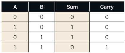
Let's start by thinking about what it would take to add two one-digit binary numbers together. Try writing out the binary sums for all the possible combinations of 0 and 1. You can use columns and carry numbers, just as you would with binary arithmetic. You should see that, because 1 + 1 requires us to carry a digit in binary to account for all possible one-digit additions, we'll need to provide for a two-digit outcome.
We can represent this in a truth table:

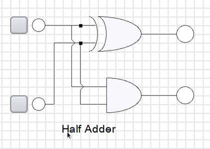
Look at each Output column in the truth table. The Carry column looks just like an AND gate's truth table, while the Sum column looks just like an XOR gate (not an OR gate, because the output shouldn't be 1 when both inputs are 1). Given that that's the case, we can make a circuit to represent this by connecting an AND gate and an XOR gate to the same inputs.
The output of the AND gate represents the carry, the second digit in the addition's result, and the XOR gate the sum, the first digit in the addition's result. You can see this circuit in the files on the disc.
Full adder

This is what's known as a half adder. It's pretty cool, right? You've now seen how controlling the flow of electricity enables us to do real work - we've managed to perform a mathematical operation just by pointing electrons in different directions!
As cool as the half adder is, however, it doesn't get us very far. Because it supports only operations on one-digit numbers, we can't count to numbers greater than 11 (3 in decimal notation).
There is such a thing as a full adder, however, and as the name suggests, it's composed of two half adders (with a slight modification). Start in the same way as before, this time doing the addition for two two-digit binary numbers.
If you do the sums with columns, it's like doing two single-digit additions. You do the addition on one column, carry the result if necessary, and then do the sum on the second column, carrying the result if necessary. Adding an arbitrarily large number, then, is 'just' a case of stringing together lots of single-digit additions, lots of half adders.
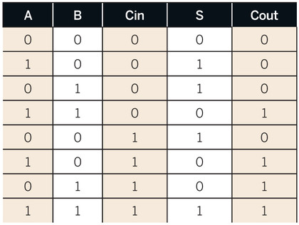
We say 'just', because if you look at the second column, there are three inputs: A, B and the carry from the previous stage. To figure out how we can do this, let's draw another truth table:

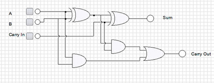
Study this table carefully, looking first at what inputs are needed to arrive at the S column, and then which inputs are necessary to arrive at the Cout column. You should see that S = (A XOR B) XOR C and Cout = (A AND B) OR (Cin AND (A XOR B)).
If we map this onto a circuit diagram, as in Figure 6, you'll see that the result is two half adders, with an additional input, and their carry bits combined in an OR gate.
This is a full adder. Alone, it's capable of adding three single-digit numbers, but they can be 'cascaded' together, by plugging the Cout of one full adder into the Cin of another, to add any sized number. Each full adder is responsible for doing 'one column' of the final sum.
A long way off
That brings us to the end of this article. We've come a long way, progressing from basic electrical circuits all the way through to making an adding machine capable of summing arbitrarily large numbers. But we're still a long way off having a real computer.
What we've created in this article would be part of a computer's Arithmetic Logic Unit. In a real computer, the ALU would be capable of many other operations, too, including subtraction, multiplication, and plain logical operations such as AND, OR and shift left and right.
The ALU would be provided with numbers to operate on, and told which operation to carry out, by a device known as the Control Unit, which in turn would fetch the instructions and operands from memory. All of these other components, however, are also made from the same basic logic gates that we've used in this article, they're just put together in different ways.