


Have you ever stopped to wonder, 'how do computers work?' Think about it for a moment. Computers are just another electrical device, like a light bulb, made of inert bits of metal and silicon.
Yet, when put together in the right way, these tiny components can store and manipulate information, and they can even have an impact on the real world.
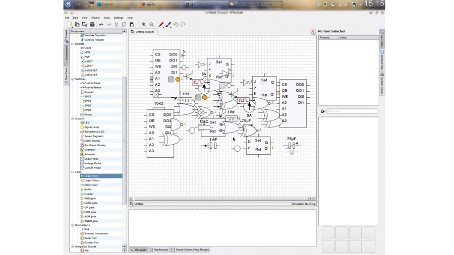
We stopped to wonder, and we decided to find out. In this article, we'll share everything we discovered. And with the aid of a piece of free software called KTechlab, we'll show you how you can put all this knowledge into practice and create your very own, crude, computing (well, adding) device.
If you want to go on and build your own computer from these designs, all you'll need is a bread board and a few components. Maplin, for example, has a comprehensive electronics catalogue.
Switching

Let's start by thinking about the light bulb. It's a simple device - you flick a switch, and it turns on. Flick the switch the other way, and it turns off. Each time you flick the switch, what you're doing is making and breaking an electrical circuit - you're controlling the flow of electricity.
This is all that really happens inside a computer, too. Lots and lots (billions) of tiny switches are controlling the flow of electricity. What makes these switches different to your light is that they're not mechanical switches controlled by people, but electrical switches that are controlled by electricity! It's a strange idea, but you can see the principle illustrated in a device called a relay, shown above.
In this electrical circuit, there's a light bulb attached to a battery. In between the bulb and the battery is a switch. While it's open, the circuit is broken and the light bulb turned off.
Underneath the switch, however, is an electromagnet. This is a device that becomes magnetic when an electrical current flows through it. When the electromagnet is switched on, the light bulb's switch is pulled downwards by the magnetic field and the light comes on. When the electromagnet is switched off, the switch swings open again and the bulb goes off.
OK, so at this point you're thinking 'somebody has still got to switch the electromagnet on'. True. We'll cross that bridge later, but for now just see how it's possible for a switch to operate based on whether there's a current flowing into it or not.
Electrical switches can be made in many different ways. Relays are one possible technique, vacuum tubes another, and then there's the transistor. Transistors are much smaller than the other two switches, and they're the switch used in modern computers.
We won't explain how they work, since this would see us sidetracked into the weird world of physics; but we will explain how to use them, since they'll form the heart of the circuits we make in the rest of this article.
Transistor as switch

To demonstrate how to use a transistor, we'll show you how to use it as a simple switch.
Take a look at Figure 2. Here, you can see that the circuit is almost identical to the relay example. The relay, however, has been replaced by the transistor.
Two of the transistor's legs are connected to the same wires as the relay's internal switch was, while the third is connected to the controlling wire. When a small current is applied to the third leg (called the base), a large current is able to flow almost uninhibited across the other two legs (the one with the arrow is known as the emitter, the other the collector). If there's no current flowing into the base, then no current can flow from the collector to the emitter.
Boolean logic
Great! Now you know how to use a transistor, but how does that help us?
To explain this, we need to step back and think a bit about boolean logic. Boolean logic is a system for determining the value of various statements, a bit like ordinary mathematics. The difference is that in the boolean system, there are only two possible values for every statement: 1 or 0 - true or false.
For instance, you can use boolean logic to evaluate the sentence 'My hands are cold'. If my hands are cold, then the boolean result of this statement is true. If they're not, it's false.
Boolean logic isn't restricted to evaluating a single statement at a time, however, since it also has operators, just like in normal maths. 'My hands are cold AND my feet are warm' is only true if both halves of the statement are true; 'My hands are cold OR my feet are warm' is true if either one, or both, of these statements are true. These kinds of statements are often summarised in truth tables, and below are the truth tables for the two operations we've seen so far:

There's one other key operation that we'll come across, called NOT. It interprets only a single statement, and inverts its value. The truth table is as follows:

Logic and transistors

Being able to evaluate whether or not a statement is true or false, with the help of operations such as AND, OR and NOT, turns out to be the basis for all computer operations. How this is so will become clear later, but for now let's look at how the humble transistor enables us to evaluate boolean statements.
The first point to note is that, whereas above we were dealing with English language statements, when it comes to electrical circuits the only tool we have at our disposal is whether a circuit is on or off, just like the lightbulb. Fortunately, boolean logic deals with precisely two values.
From now on then, 1 (on) will represent true, and 0 (off) will represent false. Let's start by creating what's known as an AND Gate, the electrical equivalent of the boolean AND operation.
Take a look at Figure 3. Here, you can see a circuit. This time there's no battery, but a fixed power source instead. To complete the circuit, we need a ground connection, which acts like the opposite side of the battery. If there's any break between the power source and the ground connection, then no electricity will flow in the circuit.
LED and transistors
You'll also need to note that the LED (light) is being used to represent the result of our boolean operation, and that the two resistors (small components used to reduce the flow of electricity - you could also turn down the voltage of the power source) are being used to protect the transistors. Without them, the transistors would operate strangely!
Now, look at the transistors. They're being used as switches, just like we did earlier. What's interesting is that they're both sat between the LED and the ground source. For the circuit to be complete (and for the LED to be on, and our result 'true') both transistors have to be conducting electricity from the collector to the emitter. If either one of them is open, no electricity flows and we get a false result.
If you want to experiment with this circuit yourself, and confirm that it really does recreate the truth table for AND, you can install KTechlab. You can drag and drop components from the left-hand side, drag wires around, and then toggle switches to see the results. Every circuit we create from now on can be recreated with KTechlab, and you can find the .circuit files on this month's DVD.
Two more gates

Before moving on, let's look quickly at how to make OR and NOT gates from transistors, too, since from these three components everything else can be built. Both circuits can be seen in the diagram above.
We'll start with the OR gate, since that's easiest. It's almost identical to the AND gate, but rather than placing the transistors inline, they're both connected to the power source and ground separately. This way, if both are off no electricity will flow, but if either one is on electricity will flow and the light come on.
The NOT gate is a bit more complicated. The light is on by default, since it's connected directly to both the power source and ground. That accomplishes the first part of our truth table. But why does the light switch off when we connect the transistor? Surely the light is still connected directly to the power source and the ground?
The reason is that in a parallel circuit such as this one, the electrical current gets divided between each branch (in this case, the transistor and the LED) in proportion to their resistance. Since the transistor has such low resistance, almost all the current goes through it and not the LED.
Of course, it's not perfect, and to ensure that the current going to the LED is low enough for it to not turn on, we introduced a resistor to reduce the current further.
Simpler symbols

That's all the basic components we need to build from their transistor building blocks. Out of these, an entire computer can be built! Pretty incredible.
Building more complex circuit diagrams on top of these will start to look messy, but fortunately KTechlab provides premade AND, OR and NOT gates, with reasonably sized and distinct symbols that will make them easier to work with. We'll be using these from now on.
Each gate's symbol is alongside the circuits we made in each figure. To show you how these can be plumbed together, take a look at Figure 5. In this figure, we've made an XOR (Exclusive-OR - true only when either input is true, not both) gate out of the other gates we constructed. We'll be making use of this in what follows, too, so note that it also has a built-in symbol, included in Figure 5.