Sign up for breaking news, reviews, opinion, top tech deals, and more.
You are now subscribed
Your newsletter sign-up was successful
However hard we try and however perfect we make our electronics, there will always be some degradation of a digital signal.
Whether it's a casual random cosmic ray or something less benign, errors creep in when data is transmitted from one computing device to another, or even within the same device.
If you view data storage on disks, DVDs and USB drives as transmissions from one device to another, they also suffer from errors.
Yet unless the 'transmissions' are obviously degraded (if you run over an audio CD with your car, for example), we're completely unaware that these errors exist.
Early error correction
It wasn't always like this. Back in the late 1940s, Richard Hamming was a researcher at the Bell Telephone Company labs. He worked on an electromechanical computer called the Bell Model V, where input was provide on punched cards.
The card reader would regularly have read errors, and there were routines that ran when this happened to alert the operators so they could correct the problem. During the weekdays, that is.
Unfortunately for Hamming, he could only get computer time at the weekends when there were no operators. The problem was magnified by the fact that the computer was designed to move on to the next computing job if no one corrected the errors.
Sign up for breaking news, reviews, opinion, top tech deals, and more.
Hence, more often than not, his jobs were simply aborted and the weekend's computation was wasted. He resolved to do something about it and pretty much invented the science of digital error correction.
At the time, there were no real error correction algorithms at all. Instead programmers relied on error detection - if you can detect that some data contains an error, at least you can ask for the data again.
The simplest method of error detection was the addition of a parity bit to the data. Suppose you're transmitting seven-bit ASCII data across a link (and again, that link could be a form of data storage). The parity bit was an extra bit tacked onto the end of each seven bits that made the number of ones in the eight bits even (even parity) or odd (odd parity).
For example, the letter J is 1001010 in seven-bit ASCII. It has three ones, so under even parity the extra bit would be one (to make 10010101 with four ones), and under odd parity the extra bit would be zero (making 10010100 with three ones).
The other end of the transmission would calculate the number of ones in every eight bits (or at least whether it was even or odd), and check that it matched the agreed upon parity scheme being used. If the calculated parity didn't match the scheme, there was a transmission error.
Early techniques
Let's take our example of Junder even parity. The sender sends 10010101, but there's a random error, a bit gets flipped and the receiver gets 10110101. Since there are five ones in this message, the receiver knows there's been a transmission error. It can't tell which bit got flipped, just that it happened.
The big problem with single parity bits as an error detection algorithm is that it can't detect when two bits are flipped during transmission (or four, or six, and so on).
Another technique that was developed in those early days was repetition - sending the same data multiple times. For example, instead of sending each bit once, we'll send it three times, so that a one gets sent as 111, and a zero as 000. In our example, our 7-bit ASCII J would be sent as 111,000,000,111,000,111,000 (I've added commas to make the triplets more obvious).
If the receiver gets 000 or 111, it assumes that the bit was transmitted without error and is either zero or one. If a single bit in a triplet is flipped, not all three bits are the same and the receiver can deduce that there was an error. Not only that simple deduction though: the receiver can also apply a crude error correction by assuming a majority vote. 001, 010, and 100 would be assumed to be triplets for a single zero bit (there are more zeros than ones), whereas 110, 101, and 011 would signify a one (more ones than zeros).
Although this error detection code is able to detect one-bit or two-bit errors per triplet, it is only able to repair one-bit errors. In doing so, it is extremely inefficient: it triples the amount of data being transmitted. If this technique were still the state of the art, your new 750GB laptop hard drive would only store 250GB of data; the rest would be parity bits.
If you think about it, what we're trying to do with parity bits and the triplets algorithm is to add extra data to the data stream so we can detect and hopefully correct errors. In a perfect world, those extra bits wouldn't be needed - they are, in a sense, redundant - but in ours, they're required for error-resilient transmissions.
One of the problems we've seen up to now is that the error detection algorithms we've discussed so far aren't very efficient. We've been able to detect one-bit errors and two-bit errors, but nothing more. Let's move on to checksums and improve our detection rate.
Checksums
Suppose you're sending your credit card number to an online store. The store wants to make sure that the number you're sending it is at least valid to a certain extent before it sends the number on to the bank for debiting. As it happens, credit card numbers are encoded with a check digit (which is the right-most digit of the full number). If you enter your credit card number incorrectly, the check digit algorithm (known as Luhn's algorithm) will trap it.
Here's how the verification works on 98762345100. Start from the right and double every second digit: 0, 0, 1, 10, 4, 6, 2, 12, 7, 16, 9. Now add up all the digits you see (that is, treat the products as two separate digits when required): 0+0+1+1+0+4+6+ 2+1+2+7+1 +6+9 = 40. The answer must be a multiple of 10, or, equivalently the answer modulus 10 is zero.
Since this is the case here, the original number is said to be valid. If there was an error in a single digit, or a transposition of two digits (one of the most common human errors that happens when writing down a long number), the algorithm will detect it because the check digit will be wrong. (The only transposition error not caught by the algorithm will be 90 to 09, or vice versa).
The check digit is an example of a checksum, a number calculated (the correct term is hashed) from a long message that is tacked onto the end of it for transmission or for storage.
There are several examples of checksums in wide use, the most popular being something small like CRC-32 or something cryptographic like SHA-256 or MD5 (less favoured these days because of academic work that has essentially cracked it). The smaller 32-bit Cyclic Redundancy Check is a great way to detect accidental or random changes to data during transmission or storage. It's easy to calculate in hardware, and is designed to detect not only errors caused by random noise but also due to burst errors, where there is a contiguous set of errors in a frame.
The larger cryptographic hashes are designed to detect malicious errors, and are designed so that it's hard to find or calculate a malicious message that has the same hash as the valid message. That's why when you download a software application, there is usually an MD5 or SHA-1 hash alongside so you can verify that the bits you got were the bits that formed the hash value.
Again, checksums are all about error detection, but not error correction. However there is a way you can use checksums to implement a simple error correction protocol called 2D parity.

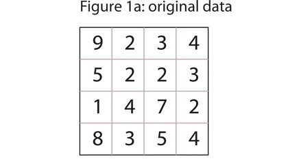
Let's illustrate this with a 16-digit number: 9234522314728354. First you write out the digits as a matrix, left to right, top to bottom - see figure 1a. Now you calculate the checksums for each row and for each column.

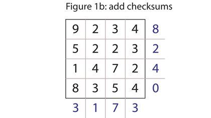
You can use any checksum you like, but for simplicity's sake we'll use the modulus 10 of the sum. See figure 1b. Now you can transmit the matrix as a longer 24-digit number, reading left to right, top to bottom again: 923485223214724835403173. The receiver can get the number and unpack it, and, to verify that it was received correctly, recalculate the checksums. If all agrees, he can extract the original 16-digit number by throwing away the checksums.

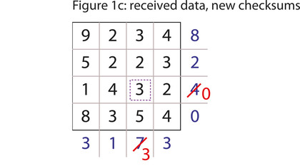
Let's suppose now that there is an error. One of the digits is transmitted incorrectly. The receiver gets Figure 1c. When he calculates the checksums, the results for row three (0) and column three (3) are incorrect.
What can he tell from this? First: that the digit at the junction of row three and column three is wrong. That's the error detection part. Second: now that he knows it's wrong, he can easily calculate what the right value should be. In both cases the checksum is four less than the correct value, so the number at (3, 3) is also four less than what it should be - that is, seven.
If you consider the problem, you can see that we can detect single errors in the original 16-digit number matrix, and in the checksum digits (if a row checksum is wrong but all the column checksums are correct, it indicates an error in the row checksum digit, for example).
Although this technique is rarely used (there are better algorithms), it does illustrate that adding redundancy in the form of checksums (or parity bits) can give you enough information to correct simple errors.
This is roughly where Richard Hamming came in. He devised a system for the most efficient way of adding parity bits to a set of data bits, such that, if there was an error, would also help identify where the error occurred. The constructed sets of data and error bits are known as Hamming codes.
Hamming codes
Let's see how to construct the (7, 4) Hamming codes (that is, the code is seven bits long, of which four bits are data bits).
1. Number the bits starting from one: 1, 2, 3, 4, 5, 6, 7. Write them in binary: 1, 10, 11, 100, 101, 110, 111.
2. All of the bits with an index that has only a single one bit are parity bits, the others are data bits. Hence, the parity bits are found at indexes that are powers of two: 1, 2, 4; and the data bits are at 3, 5, 6, 7.
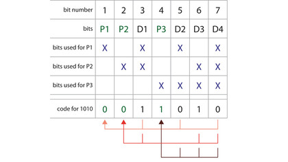
3. Each data bit is included in the calculation for two or more parity bits. In particular, parity bit one (P1) is calculated from those bits whose index has the least significant bit set: 1, 11, 101, 111, or 1, 3, 5, 7. Parity bit two (at index two, or 10 in binary), P2, is calculated from those bits whose index has the second least significant bit set: 10, 11, 110, 111, or 2, 3, 6, 7. Parity bit three (at index four or 100 binary) is calculated from those bits whose index has the third least significant bit set: 100, 101, 110, 111, or 4, 5, 6, 7.
We'll apply this to some example data: 1010. Write it out as x, x, 1, x, 0, 1, 0, where each x defines one of the (even) parity bits we need to calculate. Parity bit one is calculated from bits 3, 5, 7 (which are 1, 0, 0) and hence is one. Parity bit two is calculated from bits 3, 6, 7 and is therefore zero. Parity bit four is calculated from 5, 6, 7 and is one. The complete Hamming code for 1010 is 1011010.

Figure 2 shows this construction and calculation. Let's transmit this and assume that the receiver gets 1011110, with a single bit flipped. We can do the Hamming code calculation on the data bits, get 0010110, and therefore detect that the received code is invalid.
But there's something more we can deduce. If we look at the parity bits, we can see that bits one and four are incorrect, whereas two is right. The common data bit used for the calculation of parity bits one and four is bit five. Since the Hamming code ensures that each parity bit is calculated from a distinct set of data bits, we can conclude that it is data bit five that is incorrect: it should be zero, not one. Hence Hamming codes are not only error detection, but error correction codes.
In fact, through some pretty heavy duty mathematics we can show that Hamming codes are the most efficient way to add parity bits to detect and correct one-bit errors. Hamming codes are less used now, as better detection and correction algorithms have been devised, like Reed-Solomon codes, which can cope with burst errors rather than the less noisy random errors detected and corrected by Hamming codes.
Nevertheless, they are still used widely in RAM, but with an extra parity bit calculated from the previous seven. This extended Hamming code is known as SECDED, for single error correction, double error detection. In fact RAM tends to use a (72,64) code rather than (7, 4) because it boils down to an extra parity bit per eight data bits.