How to fly your DIY Raspberry Pi drone
Flying your own drone
Radio calibration
The RC unit is the most important part of the drone setup, as this is your sole way to communicate with the drone once the Wi-Fi dongle has been removed. Out of the box it’s unlikely that everything is 100% calibrated so you’ll need to start by checking the transmitter settings.
Depending on the transmitter and receiver combo you have selected, the setup and calibration process can be quite different. We went for the FlySky FS-i6 with the latest FS-iAB receiver.
When you’re looking to buy your own be careful that you go for this later receiver type, which is PPM compatible rather than the traditional multi channel (Although it does offer multi channel as well). This is due to the way these drones work, rather than each ESC requiring it’s own physical channel, all channels are connected through one connection.

As standard, the receiver won’t be set-up to be used for PPM so you’ll need to enter the System Setting and Select RX Setup, scroll through the menu for your handset and select PPM Output and then make sure this is switched to on.
Now you’ll need check on the transmitter's Stick Mode, again this setting is usually found in the System settings and you should be looking for Mode 2. This mode sets the left stick’s up and down control to Channel 3, the left and right to Channel 4 and on the right stick the up and down is set to Channel 2 and, finally, left and right to Channel 1.
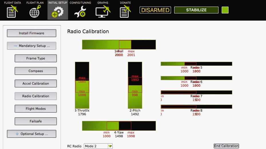
Once you’ve checked these settings it’s time to make sure that the full motion of each of the control sticks, as well as any of the other switches on the transmitter that you want to activate, are also correct. Back in APM Planner click onto the ‘Initial Setup’ tab followed by ‘RC Calibration’. Here you’ll see a series of black bars and green bars within. These green bars highlight the full range of movement that each stick has.
Click ‘Calibrate’ and then move both sticks through the full range of movement. As you do this, you’ll see the bars move and also see where the maximum and minimum levels are. You should also see in the bottom left just under the bars that the Mode is highlighted as ‘2’. Once you’ve finished the RC Unit's calibration click ‘Done’ to save the settings. Now turn off the handset and disconnect the battery.
Sign up for breaking news, reviews, opinion, top tech deals, and more.
Calibrating the ESC
The last stage is to calibrate the Electronic speed controllers (ESC). Out of the box these small devices are generally pretty similar but inevitably need calibration as well. They basically control the speed at which each of the propellers spin, so all need to be perfectly synced so all props give the same amount of lift.
Before you start, make sure the propellers have been removed, reconnect the battery and switch on the transmitter, then prime the motors by moving the left hand stick down to the bottom right position for a few seconds. The propellers should start to spin.
Watch the propellers as the spin starts and you’ll probably see that one is a little slower on the takeup compared with the others or in the case of our drone one started a lot later than the other three. Now lift the drone and increase the throttle as you tilt the drone you should feel the motors adjust to compensate the tilt.

Put the drone down and make sure that everything is switched off, and power to the drone is disconnected.
Switch on the transmitter and push the left stick (Throttle) to its maximum position. Connect the power to the drone and you should see that the LEDs will cycle through red, blue and yellow—this just shows that the drone will go into ESC calibration mode the next time you connect the power.
Disconnect the power and reconnect. Wait for the ESC to emit a sound as it beeps for each cell in your battery pack, then it will emit another two beeps to indicate that maximum throttle has been reached.
Pull the throttle to the minimum position and a long tone will be emitted to show that the minimum throttle has been reached. This also highlights that the calibration process has been completed and that the motors are primed. To check increase the throttle and all motors should spin in harmony.
Don’t kill the LiPo
One of the biggest issues with drones is power and this comes in the form of lithium-ion polymer (LiPo) batteries. They’re small, relatively lightweight and pack a punch when it comes to supplying enough power to the small motors to create lift.
Unfortunately, this power is relatively short-lived and even with the small drone that we’ve built, you really can’t expect more than five minutes of actual flight time per charge.
Once the juice runs low the drone is prone to either dropping out of the sky or in the worse case scenario flying off.
But a crashing drone is the least of your worries, when it comes to LiPo batteries it’s easy to forget that they’re extremely volatile, and if used incorrectly can explode or catch fire. The big problem with LiPos is that it’s extremely easy to abuse the small cells without realising it and we need to do everything we can to limit the possibilities of any damage to the cells or the drone itself.
Part of the beauty of building a Linux-based drone is that you can program in failsafes through the APM Planner 2.0 software. The two main settings that we’ll need to cover are 'Throttle Failsafe' and 'Battery Failsafe'. We also need to do a little more hardware calibration, this time for the power module.
This module is the extremely expensive and seemingly redundant circuit that sits between the PXFmini and battery and is what enables you to gauge the voltage of your battery and avoid over discharging.
Setting the failsafes
Before we set the limits in the Failsafes, it’s worth knowing a little about the basics of the LiPos themselves. The battery we’re using contains three cells each with a voltage of 3.7V giving a total of 11.1V. In real terms this voltage will be higher when fully charged, up to 4.2V per cell and a lower 3V per cell when discharged. More or less than these voltage values and the battery will sustain damage.
What we need to do is calibrate the power module so that it sends back the correct information about the battery so if the voltage of the battery falls below 3V per cell it knows to kick in the Battery Fail Safe and land.

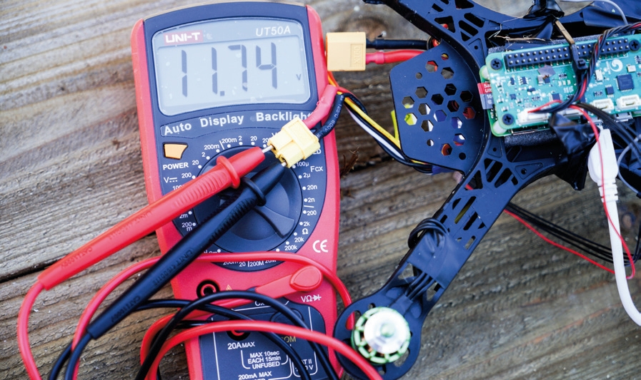
As with the ESC this needs calibrating through APM, but first we need to read the actual voltage of the battery with a voltmeter. You should find that full ycharged this is above 11.1V—in our case the battery was reading 11.9V.
Now you need to boot up the drone and wirelessly connect to your computer and open APM. Click Initial Setup > Optional Setup > Battery Monitor and click ‘3DR Iris 4 in 1 ESC’. Click the ‘Advanced’ Tab and have a look at the ‘Voltage from AutoPilot (Calced). You’ll see that this is probably reading much lower than the value you just read, click back on basic and enter the voltage you can see under the Entered Measured Value.
Now when you click back onto the Advanced tab you’ll see that the value in the Voltage from Autopilot (Calced) is now matching or at least almost identical to that of the value that’s read with the voltmeter, which will show that the power module is now calibrated.
Now to set the Failsafes in APM click Initial Setup > Mandatory > Fail Safe. Click on the ‘Land’ option for both the Throttle and Battery failsafe. You can fit a low-voltage alarm or power analyser to the battery as a further level of protection for the battery.
Once we fit GPS module we can return to this section and change these to RTL (Return to Launch). Setting these is a great place to start as mounting the GPS can take a while to get right.