


Perhaps you've fallen into the trap of thinking that a motherboard is just a slab of fibreglass for the all important processor to slot into. Well, it's time to rethink things: the motherboard is the nervous system of your PC.
It provides the essential communication pathways that enable the rest of your machine to do its job, handles the video circuitry and connections to external devices and even resists scrabbling hands trying to rip out graphics cards or rubbing all those essential components. Like all true workhorses, when it does its job, you barely notice it.
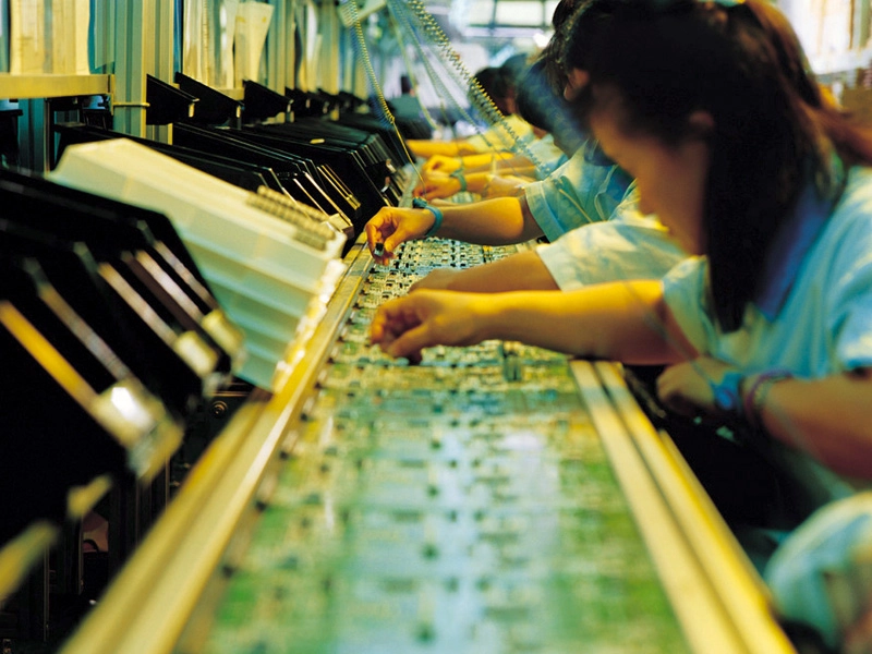
Manufacturing them remains a challenge. True, processors have features that are so small that they can't be seen with the naked eye, but the amount of technology at work when building a motherboard is no less impressive.
It's an intensive process – and one that you're about to learn in detail.
1. Raw materials
Like any other electronic item, tracing the motherboard back to its roots leaves us staring at a hole in the ground – or, to be more accurate, a couple of them.
The two dominant constituents of a printed circuit board are fibreglass – which provides insulation – and copper, which forms the conductive pathways, taking us back to their birthplaces in a sand quarry and open-cast copper mine respectively.
Turning sand into glass and copper ore into metal are processes that are hundreds of years old, but what we do with the materials next is anything but ancient.
2. Fabricating copper-clad laminate
Molten glass is extruded to produce glass fibres that are woven to create a sheet of fibreglass fabric. Next the sheet is impregnated with epoxy resin and heated to partially cure the resin; the resulting sheet is called 'prepreg'. Multiple sheets of prepreg are stacked to produce a laminated sheet of the required thickness.
Sheets of copper foil are applied to both sides of the laminate and the sandwich is placed in a heated press. This completes the curing of the resin, making the laminate rigid and causing the layers to bond together.
The result is an insulating sheet of fibreglass with copper foil on both sides: copper-clad laminate. The overall thickness of the printed circuit board (PCB) is typically 1.6mm. This means that, for a six-layer board, the fibreglass laminates will be about 0.35mm thick and the copper foil will be about 0.035mm thick.
The fibreglass is thick enough to provide adequate mechanical strength and rigidity, and the copper is sufficient for good electrical and thermal conductivity.
3. Etching away unwanted copper
A photosensitive material called photo-resist is applied to both sides of the copper-clad laminate, totally covering the copper layers. This is usually a dry film process, in which thin films of solid photo-resist are laminated onto both sides of the board using equipment that's fairly similar to an office laminator.

Now a transparent artwork showing the pattern of the PCB's pads and tracks is placed over the photosensitive copper-clad laminate, and is then exposed to ultraviolet light. Ultraviolet is used rather than visible light so the board can be handled safely in daylight.
Where the photo-resist is exposed to ultraviolet, the chemicals polymerise, forming a plastic. Since the board has two copper layers, each of which has a photo-sensitive coating, this process is carried out twice using different artworks for each side.
Next, the board is immersed in a chemical solution to develop the latent image. The developer washes away the unexposed photo-resist, leaving only material that was polymerised and which corresponds to the pad and tracks. The areas of the copper film that aren't protected by the remaining polymerised portions of the photoresist are etched away.
In an oxidation reaction, metallic copper is transformed into a copper salt, which is water-soluble and therefore washes off during the etching. For quick etching, the board passes through a chamber in which the etchant is sprayed at a high pressure and at a temperature of about 50C.
After etching, the board is washed to remove surplus etchant and the remaining photo-resist is removed using an organic solvent. The insulating fibreglass board now has a pattern of copper tracks on each side that will form the circuit's interconnections. This assembly is called a core.
However, motherboards have a multilayer construction, which means they have more than two copper layers. This means that the above process has to be carried out several times. In the case of a six-layer motherboard, two of these cores will be needed to provide four of those layers. We'll see later how the other two layers are made.
4. Building up a stack
Double-sided cores are now sandwiched together to start the creation of a multilayer PCB. Two cores are used for a six-layer board (a common figure for motherboards), but they can't be stacked directly on top of each other because this would cause the copper tracks on the top of the bottom core to short with the tracks on the bottom of the top core.
To stop this from happening, a sheet of prepreg is placed between them. Sheets of prepreg are also applied to the top and bottom of the stack before it's subjected to pressure and a high temperature to complete the curing of the prepreg and bond everything together.

For a six-layer board, the stack would comprise: prepreg / core / prepreg / core / prepreg. This means that the final result will be: fibreglass / copper / fibreglass / copper / fibreglass / copper / fibreglass / copper / fibreglass.
5. Drilling the holes
Holes are now drilled through the board. First come the mounting holes, which will be used for mechanical fixing (bolting the motherboard into the PC's case).
Second are the holes that are used to accommodate the leads of through-hole components when they're soldered to the board in a couple of steps' time.
Finally, there are the tiny holes that form vias (vertical interconnect access), which make electrical connections between the various copper layers – or will, when we get to routing, testing and QA.
Despite the use of a high-speed, numerically controlled drilling machine, drilling can be a very time-consuming process, especially if lots of different hole sizes are required. For this reason, it's common to stack boards together so that several are drilled at once, saving time and money.